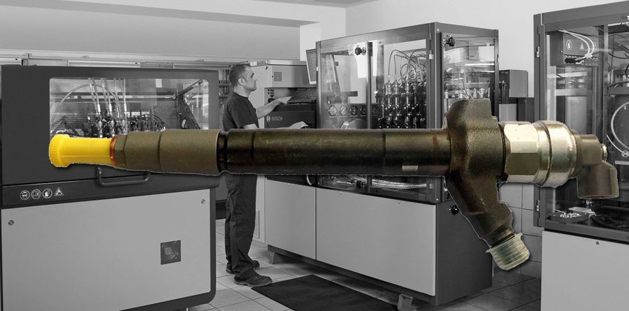
HOW TO RECONDITION A DENSO COMMON RAIL INJECTOR
Reconditioning an injector is only possible for a professional who is a highly specialized for sure, not everyone can try without the right education, experience and passion typical of who operates in this field. Each type of injector requires specific maintenance, depending on the technology and application that define it, and for now, we want to see with you how one of the most common injectors is reconditioned: the Denso Common Rail. In details, we will guide you step by step from disassembling to reassembling an injector 095000-580X = DCRI105800 mounted on 2.2L engines since 2006 for the following applications: Citroen Relay, FIAT Ducato, Ford Transit and Peugeot Boxer.
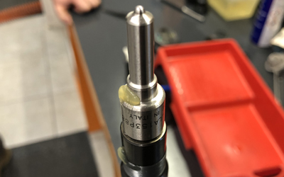
The injector code is engraved or laser-marked on its core. In the case of this Denso injector, the code section you must consider when looking for spare parts, is “095000-580” the following number could be any (from 0 to 9), this is the reason it is written as an X in our catalogue while others may indicate it as #; this difference is irrelevant.
Here below, the spare parts Seven Diesel can supply for the previous mentioned injector:
- Nozzle ND-DLLA153P 884 = 738510
- Control valve 12580
- Plunger 14580
- Nut 33705
- Butterfly shutter 33700
- Hemisphere 33701
- Closing nut 33732
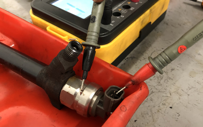
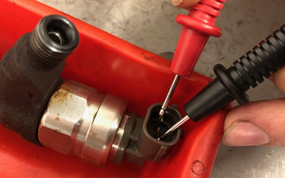
ELECTRICAL PART CHECKING. In the first instance, each diesel specialist should exclude that the potential damage is in the electrical part nor in the coil/solenoid, starting from the control of the electrical leakage by means of the insulation tester aimed to measure the effective electrical insulation of the solenoid, circulating a potential difference ranging from 250 to 1,000V. Then measure the electrical resistance between the two contacts by the Ohmeter, measuring the resistance the electricity encounters by circulating in the solenoid, making sure there is continuity between the contacts and checking the resistance matches the tolerance (not all types of injectors may have the same electrical resistance).
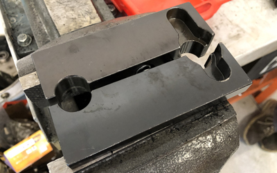
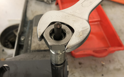
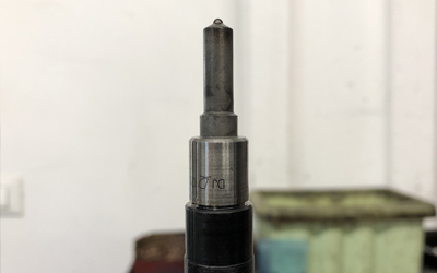
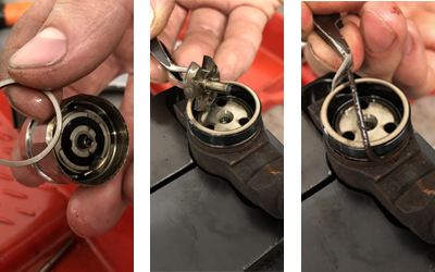
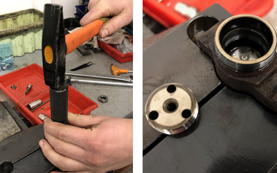
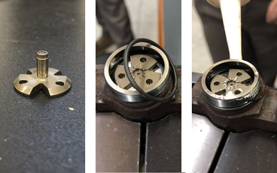
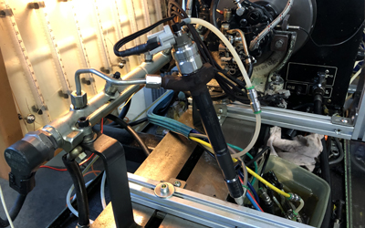
DISMANTLING THE INJECTOR: THE NOZZLE. Once the electrical parts correct functionality is sure, we can proceed whit disassembling the components. You may use the universal block on the vice (our code 10102) to facilitate and speed up the operation. We kindly advise you to start disassembling from the nozzle by unscrewing the locking nut by the right hexagonal adapter for the key (our code 10103), necessary for this type of operation. Remove the nozzle (original code reference ND-DLLA153P884 = our code 738510) and pay attention while removing the retaining pins, you may use tweezers to ease their extraction. Now overturned spring, saucer, thickness and rod on a separate shelf, being particularly careful not to lose them.
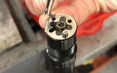
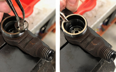
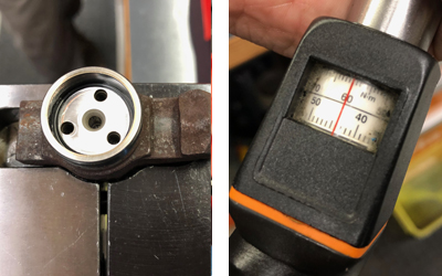
DISMANTLING THE INJECTOR: THE SOLENOID. Remove the solenoid, be careful not to damage or lose the valve and the other shims, then take away the butterfly checking the set screw condition because its disassembly may have deformed its shape; in this case it is impossible for the butterfly to be repositioned correctly, staying higher than its original position preventing the proper closure with the valve seat. Remove the gasket, the ring nut (with the appropriate disassembly tools, our code 10100 or 10101) and the control valve. Check by microscope that the latter is in good condition (not damaged, corroded or worn); during the injector assembly it is essential the hemisphere is properly positioned in its seat, i.e. the flat side towards the valve, because of the correct closure of the control chamber. An incorrect positioning of the hemisphere will affect the entire assembly of the injector and its correct functioning and even the breakage of the valve seal.
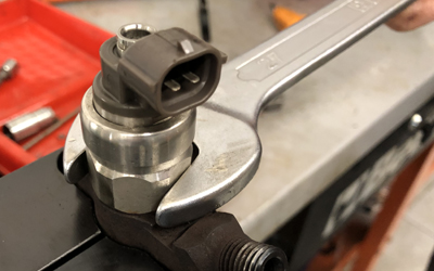
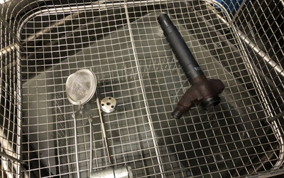
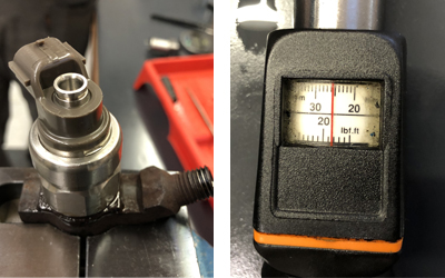
CLEANING, REASSEMBLY AND TEST BENCH. Once all the components extracted, wash them by means of the ultrasound machine, except for the electric coil. Now please proceed with the drying and assembling. Depending on the situations and conditions of the injector, it may be necessary to replace the damaged or worn out components; in most cases the most delicate components need to be replaced are the nozzle and the control valve. While the reassembling phase, put the injector back in the appropriate vice, replace the components in their seats, closing the nuts setting the torque wrench at 60 Nm, starting from the control valve, the butterfly with the flat side of the hemisphere towards the valve; it is necessary to replace the old gasket to avoid leaks. Check the condition of the shims and if necessary, evaluate a possible replacement. Put the solenoid back on and close using the torque wrench set at 25 Nm. Reposition the retaining pins, spring thickness, saucer valve and use grease for lubricating the thread, replace the nut if necessary, close by means of the torque wrench set at 60 Nm. Pay particular attention at this important phase, a too tight or, on the contrary, weak closure can affect the injector functioning.
At this point, the test bench checking is required which is generally divided into 4 phases:
- Delay time
- Flow
- Back leakage
- Coding if necessary
The setting up on the test bench and the tests vary depending on the type of test bench you use. Without an adequate test bench, it is impossible to be sure on the work done and provide any warranty to the end user. At the end of the tests you get a report indicating whether the injector works within tolerance of the master.